MCUs (Microcontroller Unit) are classified by memory Mask (mask, that is, factory program has been cured), OTP (one-time programming), Flash (programmable multiple times). It can be seen that the price of Mask is the lowest, the price of Flash is the highest, and the price of OTP is somewhere in between. From the product point of view, OTP is more widely used in electronic products, there is no need to update the program again, Flash is more suitable for learning boards, development stages. As technology continues to mature, the price of Flash is getting lower and lower.
The composition of the MCU basically has CPU, RAM, ROM, and ADC, DAC, interrupt, counter, DMA, UART, USB, etc. are external circuits that can be integrated according to actual needs. The following is a block diagram of an MCU.
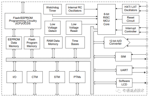
Below, Xiaobian will describe its role according to the functions contained in the block diagram, hoping to help you.
Flash/EEPROM Programming Circuitry (ICP)/OCDS:
(1) Flash: The full name is Flash Memory, which is a non-volatile storage device that is used to store programs, and simply put, the MCU is run according to what is written in this. Of course, you can also write some fixed data to addresses that are not used here.
(2) EEPROM: full name Electrically Erasable Programmable Read Only Memory, is a live erasable programmable read-only memory, in fact, it is used to store some values that are not lost when the power is lost, such as eigenvalues.
(3) ICP: full name In Circuitry Programming, is in the circuit programming, is to use the hardware way to write the program to flash, of course, there are ISP (in the system programming, through USB or UART and other interfaces to transmit data, using the bootloader BootLoader to update the Flash program, usually used for the device program update), IAP (in the application programming, simple understanding is to use a program to update another program, For example, software updates in mobile phones are this way), ISP and IAP need to occupy more memory, in the case of insufficient program space, it is still not recommended to use these two methods.
(4) OCDS: It is used for simulation, which can see the operation of the program in real time, and is usually commonly used in the development process.
Watchdog Timer: A watchdog timer is a watchdog timer that watches over the door and doesn’t let bad things happen. The simple understanding is that the operation of the program will run away, resulting in the inability to continue to run according to the track, this time the watchdog timer has played a role, the count overflows, causing the MCU to reset and restart, and the program to run from scratch.
Low Voltage Detect: Low voltage detection, when the voltage is less than the set value, it will generate an event to tell the CPU, let the CPU to process.
Low Voltage Reset: Low voltage reset, when the voltage is less than the set value, the reset will occur, to avoid the MCU when the voltage is not enough when the program operation is unstable.
8bit MCU Core: This is the brain in the MCU, which is used to process external events and internal data.
Oscillators: Crystal oscillators, there are internal RC circuits or external crystal oscillator circuits, in fact, is a square wave of a certain frequency, the CPU is running according to this beat, the speed of operation is related to this, but there is also an upper limit.
I/O: Full name Input/Output, is the interface between the CPU and external communication, the CPU can output high and low to control the device, you can also obtain external information after processing.
CTM/STM/PTM: timer, this feature is particularly useful, not only can be used as a timer, but also can be used to switch programs to run, it looks like several different functions of the program is running in parallel, in fact, or a single thread is running.
ADC: analog to digital, the principle of operation is to divide the voltage into 2ⁿ small voltages equally, and then compare the acquired voltage with the voltage of m combined, which is the converted value. n has 8, 10, 12, 16, 24, etc., the higher the bit, the more accurate it is, but the more time it takes to convert. Therefore, it should be determined according to the actual needs.
SIM: IIC and SPI, are two different ways of communication, and IIC is relatively slower than SPI. IIC is a two-wire (SCK clock, SDA data), half-duplex communication mode, that is, can only send or receive at a certain time. The SPI is 4-wire (SCS chip selection, SCK clock, MOSI master output slave input, MISO master input slave output), full duplex, that is, can be sent and received at the same time. Both the IIC and SPI clocks are provided by the host.
UART: It is an asynchronous serial communication and is also a commonly used communication method. It is a two-wire (TX, RX), full-duplex communication mode, and the speed is determined by the baud rate.
There are many more, the above is only a small part, the more you know, the more useful it is to develop products, which can greatly improve the development efficiency and integrity of the product.