
Servo Drive Basic Introduction
Servo drives are an important part of modern motion control and are widely used in industrial robots and CNC machining centers and other automation equipment. In particular, the servo drive applied to control AC permanent magnet synchronous motors has become a research hotspot at home and abroad. Current AC servo drive design commonly uses vector control-based current, speed, position three closed-loop control algorithm. The reasonable design of velocity closed-loop in this algorithm plays a key role in the overall servo control system, especially the performance of velocity control [1].
In the closed-loop servo drive velocity, the accuracy of real-time motor rotor velocity measurement is crucial to improve the dynamic and static characteristics of the velocity loop for speed control. In order to find a balance between measurement accuracy and system cost, incremental photoelectric encoder is generally used as the speed sensor, and its corresponding common speed measurement method is M/T speed measurement method. (2) the 2 control system timer switches used for speed measurement are difficult to maintain strict synchronization, which cannot guarantee the accuracy of speed measurement in measurement situations with large speed changes. Therefore, it is difficult to improve the servo drive speed following and control performance by applying the traditional speed loop design scheme of this speed measurement method [1].
Servo drive working principle
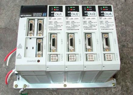
Servo Drive (Figure 1)
Mainstream servo drives all use digital signal processors (DSP) as the control core, which can realize more complex control algorithms and achieve digitalization, networking and intelligence. Power devices generally use intelligent power modules (IPM) as the core design of the drive circuit, IPM internal integrated drive circuit, while having over-voltage, over-current, overheating, under-voltage and other fault detection protection circuit, in the main circuit is also added to the soft start circuit to reduce the impact of the start-up process on the drive. The power drive unit first rectifies the input three-phase power or utility power through a three-phase full-bridge rectifier circuit to obtain the corresponding DC power. The rectified three-phase power or utility power is then driven by a three-phase sinusoidal PWM voltage inverter to drive a three-phase permanent magnet synchronous AC servo motor. The whole process of the power drive unit can be simply described as the AC-DC-AC process. The main topology circuit of the rectifier unit (AC-DC) is a three-phase full-bridge uncontrolled rectifier circuit.
With the large-scale application of servo systems, servo drive use, servo drive commissioning, servo drive maintenance are servo drive in today’s more important technical issues, more and more industrial control technology service providers on servo drive technology deep research.
Servo drive is an important part of modern motion control, is widely used in industrial robots and CNC machining centers and other automation equipment. Especially the servo drive applied to control AC permanent magnet synchronous motor has become a hot spot for research at home and abroad. Current AC servo drive design commonly uses vector control-based current, speed, position 3 closed-loop control algorithm. The algorithm in the speed closed-loop design is reasonable or not, for the entire servo control system, especially the performance of speed control plays a key role.
Servo drive basic requirements
Servo feed system requirements

Servo drive (Figure 2)
1、Wide range of speed regulation
2、High positioning accuracy
3、Sufficient transmission rigidity and high speed stability
4、Quick response, no overshoot
In order to ensure productivity and processing quality, in addition to the requirement for high positioning accuracy, but also requires a good fast response characteristics, that is, the requirement to track the response of the command signal to be fast, because the CNC system in the start, braking, requires acceleration, deceleration is large enough to shorten the transition process time of the feed system to reduce the contour transition error.
5, low-speed large torque, overload capacity
In general, the servo drive has more than 1.5 times the overload capacity in a few minutes or even half an hour, and can be overloaded 4 to 6 times in a short period of time without damage.
6, high reliability
CNC machine tool feed drive system is required to be highly reliable, work stability, with strong temperature, humidity, vibration and other environmental adaptability and strong anti-interference ability.
The requirements of the motor
1, from the lowest speed to the highest speed motor can run smoothly, torque fluctuations should be small, especially at low speeds such as 0.1r / min or lower speed, still have a smooth speed without crawling phenomenon.
2, the motor should have a large longer overload capacity to meet the requirements of low-speed large torque. General DC servo motor requirements in a few minutes overload 4 to 6 times without damage.
3, in order to meet the requirements of rapid response, the motor should have a small rotational inertia and large blocking torque, and has the smallest possible time constant and starting voltage.
4, the motor should be able to withstand frequent starting, braking and reversing.
Test platform of servo drive
The test platform of servo drive mainly has the following types: test platform with servo drive-motor inter-feeding pair of drag, test platform with adjustable simulated load, test platform with execution motor without load, test platform with execution motor dragging inherent load and test platform with online test method [2].
1 Test platform using servo-driver-motor inter-feed pair dragging
This test system consists of four parts, namely the three-phase PWM rectifier, the servo driver-motor system under test, the load servo driver-motor system and the upper computer, where two motors are interconnected by couplings. The motor under test works in the electric state and the load motor works in the power generation state. The servo-driver-motor system works in the closed-loop speed state, which is used to control the speed of the whole test platform, and the load servo-driver-motor system works in the closed-loop torque state, which changes the torque of the load motor by controlling the current of the load motor, simulating the load change of the motor under test. The platform can realize the flexible adjustment of speed and torque to complete various test functions. The host computer is used to monitor the operation of the whole system, issue control commands to the two servo drives according to the test requirements, receive their operation data at the same time, and save, analyze and display the data. [2]
For this kind of test system, the speed and torque control of the motor under test and the load equipment are carried out separately by using the high-performance vector control method, which can simulate the dynamic and static performance of the servo drives under various load conditions and complete a comprehensive and accurate test of the servo drives. However, since two servo driver-motor systems are used, this test system is bulky and cannot meet the requirements of portability, and the measurement and control circuits of the system are also complex and costly. [2]
2 Test platform with adjustable analog load
This test system consists of three parts, which are the servo driver-motor system under test, the adjustable analog load and the upper computer. The adjustable analog load such as magnetic powder brake, power dynamometer, etc., which is coaxially connected with the motor under test. The host computer and the data acquisition card control the load torque by controlling the adjustable analog load, and at the same time collect the operation data of the servo system, and save, analyze and display the data. For this kind of test system, by controlling the adjustable analog load, it can also simulate the dynamic and static performance of the servo drive under various load conditions and complete a comprehensive and accurate test of the servo drive. However, the size of this test system is still relatively large and cannot meet the requirements of portable, and the measurement and control circuit of the system is also complex and costly. [2]
3 Using a test platform with an actuator motor but no load
This test system consists of two parts, the servo driver-motor system under test and the host computer. The host computer sends the speed command signal to the servo drive, which starts running according to the command. During the operation, the host computer and the data acquisition circuit collect the operation data of the servo system, and save, analyze and display the data. Since the motor is not loaded in this test system, the size of the system is relatively small compared with the previous two test systems, and the measurement and control circuits of the system are also relatively simple, but this also makes the system unable to simulate the actual operation of the servo drive. Usually, this type of test system is only used for testing the speed and angular displacement of the system under test at no load, and cannot perform a comprehensive and accurate test of the servo drive. [2]
4 Test platform using an actuator motor dragging an inherent load
This test system consists of three parts, which are the servo drive-motor system under test, the inherent load of the system and the upper computer. The host computer sends the speed command signal to the servo driver, and the servo system starts to run according to the command. During operation, the host computer and the data acquisition circuit collect the operation data of the servo system and save, analyze and display the data. [2]
For this test system, the load adopts the inherent load of the system under test, so the test process is close to the actual working condition of the servo drive and the test results are more accurate. However, since some of the inherent loads of the system under test cannot be easily removed from the equipment, the testing process can only be carried out on the equipment, which is not very convenient. [2]
5 Test platform with online test method
This test system has only a data acquisition system and a data processing unit. The digital acquisition system collects and conditions the real-time operating status signal of the servo drive in the equipment, and then sends it to the data processing unit for processing and analysis, and finally the data processing unit makes the test conclusion. Because of the online test method, this kind of test system has a relatively simple structure and does not need to separate the servo drive from the equipment, making the test more convenient. This type of test system is based entirely on the servo drive being tested in actual operation, so the test conclusions are closer to the actual situation. However, due to the manufacturing and assembly characteristics of many servo drives, it is difficult to select the mounting positions of various sensors and signal measurement elements in this type of test system. Moreover, if other parts of the equipment fail, they will also cause adverse effects on the working state of the servo drive and eventually affect its test results. [2]
Servo drive related parameters
Position proportional gain
1、Set the proportional gain of the position loop regulator.
2, the larger the setting value, the higher the gain, the greater the rigidity, and the smaller the amount of position hysteresis under the condition of the same frequency command pulse. However, too large a value may cause oscillation or overshoot.
3、The parameter value is determined by the specific servo system model and load condition.
Position feedforward gain
1、Set the feedforward gain of the position loop.
2、The larger the setting value is, the smaller the position hysteresis under the command pulse of any frequency.
3、The feedforward gain of the position loop is large, the high-speed response characteristic of the control system is improved, but it will make the position of the system unstable and easy to generate oscillation.
4、When high response characteristics are not required, this parameter is usually set to 0 indicating the range: 0~100%.
Speed proportional gain
1、Set the proportional gain of the speed regulator.
2, the larger the setting value, the higher the gain and the greater the stiffness. The parameter value is determined according to the specific servo drive system model and load value. In general, the larger the load inertia, the larger the setting value.
3、Under the condition that the system does not produce oscillation, try to set a larger value.
Speed integration time constant
1、Setting the integration time constant of the speed regulator.
2、The smaller the setting value, the faster the integration speed. The parameter value is determined according to the specific servo drive system model and load condition. In general, the larger the load inertia, the larger the setting value.
3、Under the condition that the system does not generate oscillation, try to set a smaller value.
Speed feedback filtering factor
1, set the speed feedback low-pass filter characteristics.
2, the larger the value, the lower the cut-off frequency, the less noise generated by the motor. If the load inertia is large, the setting value can be reduced appropriately. Value is too large, resulting in slower response and may cause oscillations.
3, the smaller the value, the higher the cut-off frequency, the faster the speed feedback response. If higher speed response is required, the setting value can be reduced appropriately.
Maximum output torque setting
1、Setting the internal torque limit value of the servo motor.
2、Set the value as a percentage of the rated torque.
3、At any time, this limit is valid for positioning completion range.
4、Setting the positioning completion pulse range under the position control mode.
5、This parameter provides the basis for the driver to judge whether the positioning is completed in the position control mode. When the number of remaining pulses in the position deviation counter is less than or equal to the set value of this parameter, the driver considers that the positioning is completed and the place switch signal is ON, otherwise it is OFF.
6, in the position control mode, the output position positioning completion signal, acceleration and deceleration time constants.
7, the setting value is to indicate the acceleration time of the motor from 0 to 2000r/min or the deceleration time from 2000 to 0r/min.
8, acceleration and deceleration characteristics are linear arrival speed range.
9, setting the arrival speed.
10, in non-position control mode, if the motor speed exceeds this setting value, the speed arrival switch signal is ON, otherwise it is OFF.
11、Under position control mode, this parameter is not used.
12、It has nothing to do with the direction of rotation.
Servo driver application areas
Servo drive is widely used in the field of injection molding machine, textile machinery, packaging machinery, CNC machine tool field, etc.
Servo drive controller features
Speed regulation ratio 1:5000
Rotation ratio 0.3:1500
With position control
With zero speed lock
Overload capacity 200[%]-300[%]
High starting torque
Rotational speed independent of load
Triple closed-loop control
Servo drive related differences
1、Servo controller can easily convert operation module and fieldbus module through automation interface, while using different fieldbus modules to realize different control modes (RS232, RS485, fiber optic, InterBus, ProfiBus), while the control mode of general-purpose inverter is relatively single.
2, servo controller directly connected to the resolver or encoder to form a closed-loop speed and displacement control. And general-purpose inverter can only form an open-loop control system.
3 servo controller control indicators (such as steady-state accuracy and dynamic performance, etc.) is better than the general-purpose inverter.