With the growth of new energy vehicles over the years, The demand for HMI display for EV charging piles is increasing, and there is a strong demand for better and more convenient charging piles. The planning of the charging pile is a two-dimensional code mobile payment system designed according to the current demand. The system involves mobile app and applet scanning QR code, downloading and installing applications, registering a user name, assigned ID, registered license plate, mobile phone number, and other information, and realizing associated authentication and authorization.
Without recharging, fees can be automatically deducted from the user’s mobile wallet after charging.
This processor-based GUI design helps speed time-to-market and helps customers design cost-effective human-machine interface (HMI) solutions, such as: charging infrastructure for electric vehicles (EV), and infrastructure for EV power supply equipment (EVSE).
This project shows the general idea of developing HMI and some functions of STONE Designer, software for designing graphics. STONE Designer is compatible with OS, Windows, and Linux systems with HMI screens to meet the needs of low-end to high-end applications.
This article does not cover the process of charging hardware and charging pile, nor does it introduce the implementation of the mobile app, applet, and cloud server in detail. This paper focuses on the implementation of charging pile on the new development platform of serial port TFT screen STWI056WT-01, such as St file creation, interface page addition, button parameters, image component parameters, real-time clock parameters and adjustment instructions, label assignment, two download methods of the new development platform, etc.
The narrative framework is:
Introduction to man-machine interface
Interface widget making
Interface download
Human-computer interaction instruction
Communication programming between MCU and STONE HMI display
1. Introduction to HMI display for EV charging
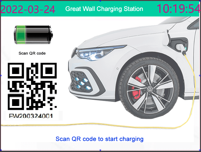
The charging pile standby interface is shown in figure (1).
Through the QR code login authorization of the mobile app and applet scanning interface, identify and activate the Great Wall charging pile equipment. After collecting the customer information, judge that the vehicle charging interface is connected correctly, and turn to the charging real-time parameter monitoring page, as shown in figure (2).
The user name, ID, and license plate number are displayed on the charging parameter display page to facilitate the user to check. The monitoring page also collects the real-time voltage uploaded by the charging module The current (the current will be controlled at different stages and charging speeds) will also accumulate the charging time and display dynamically. With the charging process, the cost will also be displayed on the screen and change dynamically. When the charging is completed (trickle replenishment will be made after fast charging, which is the internal work of the charging module, which is not involved in man-machine programming here), manually press the full changed / the end button to enter the thanks page, as shown in figure (3).
On the thanks page, but the charging module sensor recognizes that the charging gun is reset, the interface can automatically jump to the charging pile standby interface – figure (1).
If you scan the code, you can also log in again to enter the charging real-time parameter monitoring page – figure (2).
 Figure (1) charging pile standby interface
 Figure (2) charging real-time parameter monitoring page
 Figure (3) thank you page
2. HMI display Interface widget makin
First, create a new project in the STONE designer platform, fill in the project name, the resolution of the selected serial port screen 640 * 480, project path, etc. The project name filled in here will be used in the following debug download to generate compiled files (the project name is used as the compilation folder name). See figure (4)
 figure(4) create a New project interface
The work involved includes:
Add window
Import image
Put in a digital clock
Production interface switching button
Label layout display parameters
Additive GIF graph
The following are detailed one by one.
1) Add window
In the project setting part on the upper left of the project, right-click on the project name. At this time, select a new window in the pop-up menu to add Window1, window2 in turn, and the home is automatically generated when creating a new project_ Page is the startup page. When you right-click on windows1, the pop-up menu can select Copy, delete and set as home. Select set as home to replace the startup page. Double click windows1 to expand or store widgets in windows1.
2) Import image
This project starts with home on three pages_ Import background pictures on-page, Window1, and window2. This step must be done first because it is the background! Before importing the image background, all the widgets made will be “blocked” by the background. If it is a button, you will find that they can’t realize the design function. Therefore, remember to import the background first and then make other widgets.
Press and hold the image icon in the menu bar of the parts list and drag it to the interface. The background image is of course 640 * 480 pixels. There is no need to use the mouse for homing, and the keyboard operation is faster and more accurate. As shown in figure (5), fill in X, y, W, and h in the upper right parameter part. In addition, the image at the bottom of the figure (5) can select the background image. You must add a background picture to the platform before selecting. The method of adding is to click “+” in the image tab at the bottom left and select the UI pictures made by the artist one by one according to the guidance (the copy of these pictures to the display memory will be mentioned when downloading the interface later).

Figure (5) starting point coordinates and width height positioning
3) Put in a digital clock
Press and hold the digital clock icon in the menu bar of the parts list and drag it to the design place in the interface. Refer to figure (6) to set text color, font size, and format for the attributes of a digital clock. Note that the PC font library is not necessarily the same as the display font library.
The effect displayed on the PC interface will be different from that displayed on the serial port display screen. The time and date here are displayed in two widgets, as shown in figure (1), figure (2), and figure (3). If space allows them to be displayed together, set the format to y-mm-dd HH: mm: SS. If you don’t want to display seconds, format: HH: mm can be used. HMI display for EV charging.


Figure (6) attributes of digital clock
4) Production interface switching button
On the charging parameter monitoring page of windows1, as shown in figure (2), there is a button full changed / the end at the bottom right. Clicking it will switch to the thanks page of windows2. Similarly, press and hold the button icon in the menu bar of the parts list and drag it to the design place in the interface. Its properties are shown in figure (7). To switch the page to window2, you need to select open window for user define, and then select window2 for target name Make sure that the position of the button in the picture and the background do not match the position of the button in the picture, and then make sure that the button is placed in the background. In addition, home width, back window, set value, and other options are available in the user definition. HMI display for EV charging.

figure(7)
5) Label layout display parameters
Similarly, press and hold the label icon in the menu bar of the parts list and drag it to the design place in the interface. Set the text color and font size in the label attribute section, and adjust the position and font size according to the displayed real-time voltage (label7), current (label8), charging time (hour — label10, minute — label11, second — label12), cost (label9) and another background. Here, the important thing is the name. The names of each unit should be distinguished. The data uploaded from the charging module should be in place according to the name. Don’t be arrogant.
6) Additive GIF graph
In figure (2), the battery icon on the right is a GIF dynamic diagram, showing the current state of the battery being charged. Similarly, press and hold the GIF icon in the menu bar of the parts list and drag it to the design place in the interface. Gif image import is similar to the image. Similarly, add a GIF image with “+” under the image label on the left. Then select the GIF image in the image of the Properties section. HMI display for EV charging
3. Interface download
There are two methods: A and B.
Copy through USB flash disk;
Copy via USB cable.
Method A:
There are the following steps:
Save the man-machine interface project file;
Click debug – “download” under the main menu, select the target folder, and a subfolder with the same name as the project will be generated under the selected folder;
Copy the “default” folder under the shell subfolder to the STONEdirectory of the USB flash disk;
Disconnect the power supply of the display screen and turn the dial switch on the back of the display screen to the position “host”;
Insert the USB flash disk into the USB interface of the display screen, disconnect other unnecessary connections, and power on;
After the startup is stable, press the reset button on the back of the display screen. After the indicator light is stable again, power off and restore the dial switch to the “device” position above;
Check whether the download is successful. Otherwise, repeat steps 4, 5, and 6 above until successful.
Method B:
Click debug — “download” under the main menu, select the target folder, and the selected file will be displayed
A subfolder with the same name as the project is generated under the folder; Use the self-contained USB communication cable to directly connect the computer and the USB interface of the display screen (the USB interface of the USB drive in method a), and copy the raw / default/folder under the subfolder of the same name of the project to the “default” folder of the storage directory of the display screen! Note that you can delete the other seven folders except the image folder under the “default” folder first. The image folder may be occupied by the system when the machine is turned on, and an error will be prompted when writing. You can see that the image folder contains standard label pictures. If new labels and pictures are added, you can manually copy them after comparing the image / XX folder file. This method is similar to real machine debugging, which is more convenient and fast!
4.Human Machine Interface (HMI) for EV Charging instruction
The STONE instructions used are:
Digital clock adjustment
Tag value update
Page conversion
A. Digital clock adjustment
It is often necessary to set the clock for the first power on. There are six digital clock widgets in the three interfaces of this project, with different names. When powering is on, just reset clock1, and the others will be synchronized automatically. Note that the format of the digital clock attribute is set to y-mm-dd HH: mm: SS, which can be adjusted according to the actual display situation. If you don’t want to display seconds, format: HH: mm. The setting instructions are unified as follows:
ST<{“cmd_code”:”set_date”,”type”:”digit_clock”,”widget”:”clock1″,”date”:”2022-03-24 12:23:46″}>ET
B. Tag value update
The real-time voltage (label7), current (label8), charging time (hour — label10, minute — label11, second — label12) and cost (label9) displayed on the Window1 page are all label components, which are transmitted by the charging module, and MCU sends them to the serial port touch screen through label related instructions. Label related instructions:
set_ text Set the text displayed by label
set_ value Set the value displayed by label
get_ text Get the text displayed by label
get_ value Get the value displayed by the label (float)
give an example:
Set text:
ST<{“cmd_code”:”set_text”,”type”:”label”,”widget”:”label4″,”text”:”Frank”}>ET
ST<{“cmd_code”:”set_text”,”type”:”label”,”widget”:”label5″,”text”:”123456″}>ET
Set value:
St < {“cmd_code”: “set_value”, “type”: “label”, “widget”: “label9”, “value”: 1.23, “format”: “%. 2F”} > et set fee 1.23
ST<{“cmd_code”:”set_value”,”type”:”label”,”widget”:”label8″,”value”:25,”format”:”%02d”}>ET
Set current 25 A
Get text:
ST<{“cmd_code”:”get_text”,”type”:”label”,”widget”:”label6″}>ET
Format values: %d,%02d,%03d,%04d,%05d,%06d,%f,%.1f,%.2f,%.3f,%.4f,%.5f,%.6f
C. Page conversion
Window related in the command:
open_ win Open any window (Windows running in the background can also be opened with this command, recommended)
close_ win Close any window (not recommended, use with caution)
back_ win Return to the upper window and close the current window (do not cache the data of the current serial port)
back_ win_ to Return to any window in the upper layer, and other opened windows run in the background
back_ home Return to the main window, do not close the previously opened window, and other windows run in the background;
give an example:
Open the Window1 window
ST<{“cmd_code”:”open_win”,”type”:”window”,”widget”:”window1″}>ET
Close label_ Value window
ST<{“cmd_code”:”close_win”,”type”:”window”,”widget”:”label_value”}>ET
Return to the upper window:
ST<{“cmd_code”:”back_win”,”type”:”window”}>ET
The name of the upper layer returned is label_ Value window, which closes all windows above the window. It is generally applicable to multi-level windows
ST<{“cmd_code”:”back_win_to”,”type”:”window”,”widget”:”label_value”}>ET
Return to label_ Value window
ST<{“cmd_code”:”back_win_to”,”type”:”window”,”widget”:”home_page”}>ET
Return to main window
Return to main window
ST<{“cmd_code”:”back_home”,”type”:”window”}>ET
PS: the main window cannot be closed
1. Communication programming between Arduino MCU and STONE HMI display
Programming in Arduino environment, baidu input method is unloaded to realize normal English input. In addition, the above instructions should be changed in Arduino environment. As follows:
St < {“cmd_code”: “set_value”, “type”: “label”, “widget”: “label9”, “value”: 1.23, “format”: “%. 2F”} > et the above setting fee is 1.23, which should be written in Arduino program as:
Serial. println(F(“ST<{”cmd_code”:”set_value”,”type”:”label”,”widget”:”label9”,”value”:1.23,”format”:”%.2f”}>ET”));
The cost price is a floating-point variable, and the transmission method is serial Print (price, 2), with 2 decimal places reserved. Serial. Write (price) can only transmit 0-9, single digits. And because it is a variable, it needs to be transmitted separately. See the program code below. HMI display for EV charging.
The program code of video effect is as follows:
STONE HMI display for electric vehicle charging infrastructure project video
Related posts:
Touch Screen for Automated Feeding System
Arduino Tutorial: STONE STWI101WT-01 HMI Display and Arduino
STONE TFT Screen ventilator Project: HMI Design, Control Creation, Hardware Connection and Command Testing
Record Medical Surgery Notes with STONE Serial LCD Screen
Thermal Print Head for a Parking Management System Based on Raspberry Pi Pico and STONE TFT LCD
Portable Monitor with STONE serial Touch Screen and ESP32
Arduino Tutorial for Beginners LY-F2 of Seven Star Bug +STONE Serial Screen
STONE HMI TFT LCD Arduino Development Project Ideas
STONE HMI Display Esp32 Weather Station
How TFT LCD Touch Screen Display Works
.webp "Tutorial: STONE HMI display for EV charging infrastructure project")